

Introduction of Section of Solid:
Some times the objects are so complicated that, it becomes very difficult to visualize the object with the help of its front view and top view.
Some objects are hollow. Their internal details are not visible with the help of simple front view and top view.
In such cases the object is cut by some imaginary cutting plane to understand internal details of that object.
The action of cutting is called SECTIONING a solid & The plane of cutting is called SECTION PLANE.
Types of Cutting Planes and Their Representation:
1: PRINCIPAL PLANES
(a) Frontal or Vertical Cutting/ Section Plane
(b) Horizontal Cutting/ Section Planes

2: AUXILIARY PLANES
(a) Auxiliary Vertical Plane (A.V.P.); Inclined to VP & Perpendicular to HP
An AVP. appears as a straight line in its top view. The straight line is its HT. So an AVP always cuts TV of a solid.
(b) Auxiliary Inclined Plane (A.I.P.); Inclined to HP & Perpendicular to VP
An AIP appears as a straight line in its front view. The straight line is its VT.
So an AIP always cuts FV of a solid
(c)Profile Cutting / Section Planes ; Perpendicular to both & VP
(d) Oblique Section Plane
Remember:
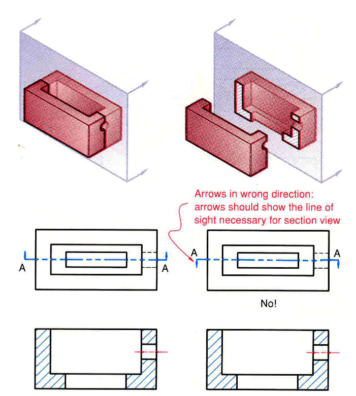
- After launching a section plane either in FV or TV, the part towards observer is assumed to be removed.
- As far as possible the smaller part is assumed to be removed.
Section Line or Hatch Line Properties:
- Section lines or cross-hatch lines are added to a section view to indicate the surfaces that are cut by the imaginary cutting plane.
- Different section line symbols can be used to represent various types of materials.
- However, there are so many different materials used in engineering design that the general symbol (i.e., the one used for cast iron) may design that the general symbol (i.e., the one used for cast iron) may be used for most purposes on engineering drawings.
- The actual type of material required is then noted in the title block or parts list or as a note on the drawing.
- The angle at which lines are drawn is usually 45 degrees to the horizontal, but this can be changed for adjacent parts shown in the same section. Also the spacing between section lines is uniform on a section view.
- Section lines should not run parallel or perpendicular to the visible outline.
- If the visible outline to be sectioned is drawn at a 45degree angle, the section lines are drawn at a different angle, such as 30 degrees.

- Avoid placing dimensions or notes within the section lined areas. If the dimension or note must be placed within the sectioned area, omit the section lines in the area of the note.

- Section lined areas are bounded by visible lines, never by hidden lines, because the bounding lines are visible in the section view.

Types of Section Views:
- Full sections
- Half sections
- Offset sections
- Offset sections
- Broken-out sections
- Revolved sections
- Removed sections
Section of Solid Introduction:
Section of Solid First Soved Example Video:

