

Solids:
A 3-D object having length, breadth, and thickness and bounded by surfaces which may be either plane or curved, or combination of the two.
Classified under two main headings:
- Polyhedron
- Solids of revolution
Polyhedron further classified into:
- Regular polyhedron–solid bounded only by plane surfaces (faces). Its faces are formed by regular polygons of the same size and all dihedral angles are equal to one another.
- Other polyhedra–when faces of a polyhedron are not formed by equal identical faces, they may be classified into prisms and pyramids.

- Prism –a polyhedron formed by two equal parallel regular polygons, end faces connected by side faces which are either rectangles or parallelograms.
- Pyramids –a polyhedron formed by a plane surfaces its base and a number of triangles as its side faces, all meeting at a point, called vertex or apex.
- Axis –the imaginary line connecting the apex and the center of the base.
- Inclined/slant faces –inclined triangular side faces. Inclined/slant/longer edges–the edges which connect Inclined/slant/longer edges–the edges which connect the apex and the base corners.
- Right pyramid–when the axis of the pyramid is perpendicular to its base.
- Oblique pyramid–when the axis of the pyramid is inclined to its base.
Solids of revolution –when some of the plane figures are revolved about one of their sides –solids of revolution is generated.
Cylinder: When a rectangle is revolved about one of its sides, the other parallel side generates the cylinder.
Cone: When a right triangle is revolved about one of its sides the hypotenuse of the right triangle generates cone.
Sphere: When a semi-circle is revolved about one of its diameters, a sphere is generated.
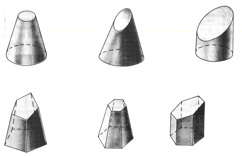
Truncated and frustums of solids –when prisms, pyramids, cylinders are cut by cutting planes, the lower portion of the solids (without their top portions) are called, either truncated or frustum of these solids.
If the cutting plane is parallel to the base then the lower remaining portion is known is Frustum of that solid.
If the cutting plane is inclined to the base then the lower remaining portion is known is Truncated solid.
Visibility: when drawing the orthographic views of an object, it will be required to show some of the hidden details as invisible and are shown on the orthographic views by dashed lines.
Rules of visibility
All outlines of every view are visible: the outlines of all the views are shown by full/solid lines.
Rules for Drawing the projection of Solid:
Step 1: Assume Initial Condition and Draw First Projection.
1. Check its Axis inclination.
A. If Solid axis is inclined to HP, assume it perpendicular to HP.
So Its TV will show the true shape of base of given solid.
B. If solid axis is inclined to VP, assume it perpendicular to VP
So it’s FV will show the true shape of base of given solid.
and We will start with true shape of base.
Step 2: Consider Axis inclination and draw second projection.
Step 3: Now finally consider side/edge inclination and draw third projection.
Note: If any side or edge is inclined by any principal plane or kept in any plane assume and perpendicular to XY line while drawing true shape i.e. first projection.
Rules for Hidden and Solid Lines:
When making second and third projection some time it is difficult to identify which line will be hidden (dotted) and which line will be visible (solid).
Rule 1: First Joint all extreme points and make a close loop and ensure that all points are inside of this loop.
Rule 2: Now check the furthest point from XY line
All the lines passing through the furthest point from XY Line must be Solid line (Visible).
Red point in the example.
As in second FV Furthest point is a’ and lines passing through this point are ab, ad, and a1 so these lines in TV must be solid.
Rule 3. FinallyNow check nearest point from XY line
All the lines passing through the nearest point from XY line must be dashed line (hidden) Green point in the example.
As in second FV nearest point is 3′ and lines passing through this point are 32, 34, and 3c these lines must be dashed line. One point must be remembered here if already any line mentioned here has been already drawn solid either by first rule i.e. outer boundary loop making or second rule furthest point rule, then it will remain solid.
Rule 4: Two solid lines or two dashed lines never intersect each other only possible cash is solid line intersects the dashed line.
Rule 5: If any line is remaining to draw then repeat 2 and 3 rule with second furthest and nearest point and then so on……
For clear understanding go through next example projection II and III.

Projection of Solid Introduction:
Projection of Solid Solved Example Tutorial:
Solved Exampled 3:
Solved Exampled 4:
Problem: cube solid diagonal perpendicular to VP.
Power Point Presentation:

